Wire Emergy’nX: KNX bus, 9-30 V DC power supply and Ethernet
Emergy’nXAdministratorInstaller
Emergy’nX gateway: DIN rail mounting, connectors, front panel and wiring diagram
Emergy’nX mounts on a DIN rail and connects to three things: the KNX bus, a 9-30 V DC auxiliary power supply and an Ethernet network with Internet access. The specifications, connectors, LEDs and wiring diagram below help you prepare the electrical cabinet before commissioning.
Intended for the installer preparing the electrical cabinet. Once the gateway is wired, follow commissioning in Can’nX Cloud.
Technical specifications
Section titled “Technical specifications”| Specification | Value |
|---|---|
| KNX bus | KNX TP, S-Mode (ETS), 30 V, 5 mA |
| Auxiliary power supply | 9-30 V DC, 2 W |
| Network | Ethernet 10/100 Mbit/s, RJ45 socket |
| Mounting | DIN rail, 2 modules |
| Dimensions | 35 mm wide, 90 mm high, 70 mm deep |
| Operating temperature | -25 °C to +55 °C |
Locate the connectors and the front panel
Section titled “Locate the connectors and the front panel”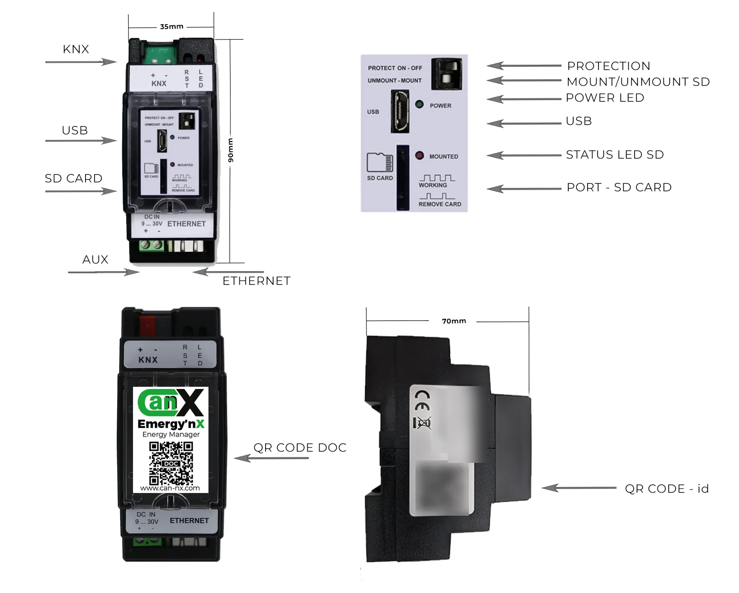
| Marking | Location | Role |
|---|---|---|
| KNX + and − | Top terminal block | Connection to the KNX bus |
| DC IN 9 … 30V + and − | Bottom terminal block, left | Auxiliary power supply |
| ETHERNET | Bottom socket, right | Local network and Internet access |
| PROTECT ON - OFF | Front panel | In the ON position, blocks access to the gateway’s local configuration site and greys out its configuration buttons in Can’nX Cloud |
| UNMOUNT - MOUNT | Front panel | Reserved for maintenance operations by support |
| POWER | Green LED, front panel | Power indicator |
| MOUNTED | Red LED, front panel | SD card status, according to the printed patterns WORKING and REMOVE CARD |
| SD CARD | Front panel | µSD card reader, 32 GB maximum, for KNX telegram logging |
| USB | Front panel | USB port |
| DOC QR code | Front label | Documentation QR code |
| Identification QR code | Side label | Identifier scanned when adding the gateway in Can’nX Cloud; the label also shows the MAC address and the serial number (S/N) |
Note the MAC address and the serial number before closing the cabinet: they let you add the gateway without scanning the QR code.
Wire the gateway
Section titled “Wire the gateway”-
Fix the gateway on the DIN rail of the cabinet.
-
Connect the KNX bus to the KNX terminal block, observing the + and − markings.
-
Connect the output of a 9-30 V DC power supply to the DC IN terminal block, + and −. The power supply must provide at least 2 W.
-
Connect the ETHERNET socket to a switch or to the Internet router with an RJ45 cable.
-
Switch on the power supply.
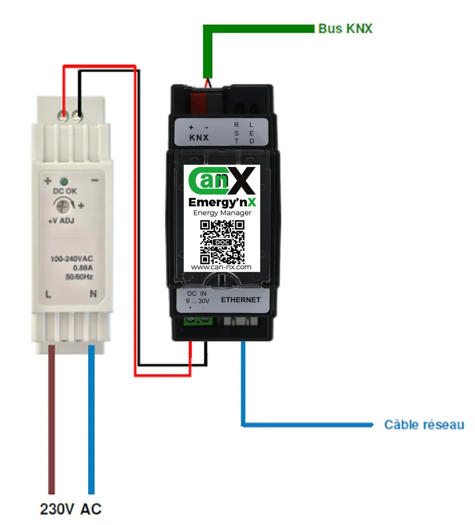
The KNX bus is not needed for initialization in Can’nX Cloud: the power supply and Internet access are enough. Connected to the router, the gateway connects to the Can’nX cloud by itself, without any change to the local network settings.
Check the result
Section titled “Check the result”- In Can’nX Cloud, after commissioning, the gateway appears online in the project list.
- On its page, Protection mode is not Locked: the PROTECT switch is set to OFF.
Troubleshooting
Section titled “Troubleshooting”| Symptom | Cause and action |
|---|---|
| The POWER and MOUNTED LEDs do not go out at startup | The gateway did not start correctly. Check the connections and the power rating of the power supply. |
| Gateway offline in Can’nX Cloud and local site unreachable | Check the 9-30 V DC, 2 W power supply, the RJ45 cable and the network’s Internet access. |
| Gateway offline in Can’nX Cloud, local site reachable | If DHCP is not enabled on the gateway’s local site, enable it to test. Have the network administrator check that the gateway can access the Internet, and disable IPv6 for the devices on the router’s local network. |
| Configuration buttons greyed out on the gateway page, Protection mode Locked | The PROTECT switch is set to ON. Set it to OFF. |
For other situations, see Emergy’nX troubleshooting. If the problem persists, write to support@can-nx.com with the gateway name, its serial number and the state of the LEDs.